| Oracle® Communications Diameter Signaling Router Getting Started Release 8.3 E88995 |
|

 Previous |
 Next |
| Oracle® Communications Diameter Signaling Router Getting Started Release 8.3 E88995 |
|
|
Previous |
Next |
The DSR can be deployed either as a core router that routes traffic between Diameter elements in the home network, or as a gateway router that routes traffic between Diameter elements in the visited network and the home network.
In DSR topology, the OAM server function is split into Network OAM (NOAM) servers and System OAM (SOAM) servers. A DSR with a pair of NOAM servers is connected to multiple DSRs with SOAM servers in the network. Each DSR with NOAM servers is connected to one or more mated pairs of SOAM servers, or a triplet if using Policy Diameter Routing Agent (Policy DRA). The DA-MP servers reside with a pair of SOAM servers that interact directly with the MP servers on that DSR.
Figure 3-1 provides an overview of the DSR architecture.
Diameter Signaling Router Topology
The role of the DSR NOAM server is network scope. The role of the DSR SOAM is managing a DSR Signaling NE.
As shown in Figure 3-1, there are NOAM servers, SOAM servers, and MP servers.
Figure 3-1 Diameter Signaling Router Diagram
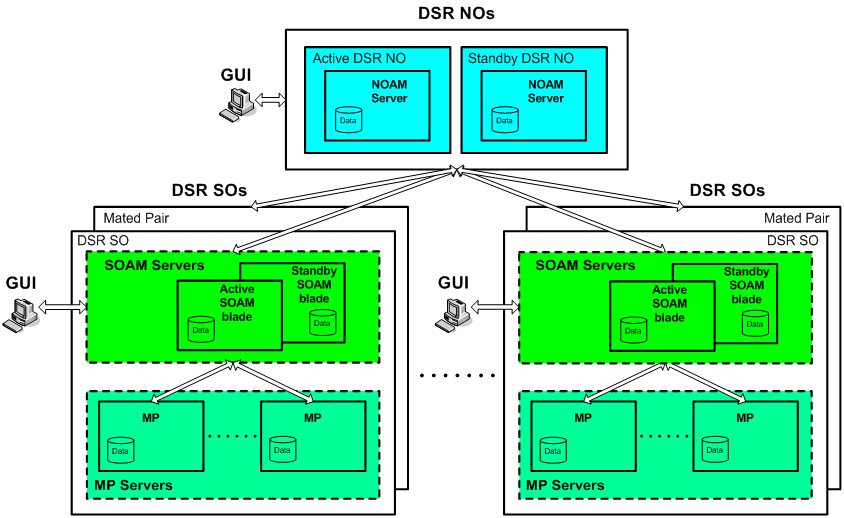
The MPs process the database updates from NOAM servers and SOAM servers and perform the real-time signaling. The MP servers also supply the Platform MEAL data, Diameter signaling MEAL data, and DSR Application MEAL data to SOAM servers. The SOAM servers retain the Diameter signaling MEAL data and DSR Application MEAL data if it is site specific, and merge the Platform MEAL data to the NOAM servers. Network-scoped MEAL data is forwarded to the NOAM).
Deployment with SDS
DSR deployments that include support for the DSR Full Address Based Resolution (FABR) application must be deployed with the Subscriber Database Server (SDS). The SDS is used to provision the FABR subscriber data.
The SDS/DP system consists of a Primary Provisioning Site, a Disaster Recovery (DR) Provisioning Site, and DSR Signaling Site servers with redundant DP SOAM servers and DP servers. Each Provisioning Site has an Active/Standby pair of servers in a high availability (HA) configuration and a third server configured as a Query Server.
The DSR SOAM and the SDS SOAM servers are run on some DSR OAM server using virtualization technology. It is assumed that most deployments that support both DSR and SDS deploy the DSR NOAM on servers since this is how the SDS NOAM is deployed. Small deployments that minimize the amount of hardware investment require the DSR NOAM to be deployed as a virtual server on the OAM server. This requires running three virtual machines (VMs) on the server – DSR NOAM, DSR SOAM, and SDS SOAM.
